AN02003: SPDIF/ADAT/I²S Receive to I²S Slave Bridge with ASRC#
Introduction#
This application note demonstrates a practical application of the XMOS Sample Rate Conversion library in a system that receives samples from a digital input (either S/PDIF, ADAT or I²S slave) and outputs them over an I²S slave interface operating on a different master clock domain. All of the logic to detect and change sample rates and channel counts is included and may be used as the basis for new designs. In addition to asynchronous clocking support it can perform major rate changes between the standard audio sample rates of 44.1, 48, 88.2, 96, 176.4 and 192 kHz.
Samples received via the selected input interface i.e. I²S, S/PDIF or ADAT are input into an Asynchronous Sample Rate Conversion (ASRC) block, the output samples from this block are then provided to the I²S output interface.
The performance of the underlying ASRC function is as follows:
THD+N: (1 kHz, 0 dBFs): better than -130 dB
SNR: 135 dB (or better)
The I²S “output” interface can also receive samples at the output rate. Samples received on this bus, from the ADC, are forwarded to either ADAT or S/PDIF transmitters directly (where enabled) at the I²S output rate without any sample rate conversion.
In the example application the I²S output subsystem is connected to an external DAC. This uses a fixed frequency master-clock generated by the xcore.ai application PLL (derived from the xcore.ai system clock) to generate word and bit clock signals to the xcore. This clock is clearly unrelated to any clock that maybe derived from the input interface (I²S/SPDIF/ADAT). This means that, even if operating at the same nominal sample rate, the clocks will not be synchronized (i.e. may drift) and consequently an ASRC is required to properly stream artefact free audio between these two interfaces.
The application provided along side this application note is called app_an02003.
There are three build configurations for this application, each supporting a different input
digital audio sources. Details of each of the build configurations are listed in Table 1.
Config name |
Input channel count |
Output channel count |
Additional signal path |
|---|---|---|---|
I2S |
2 |
2 |
N/A |
SPDIF |
2 |
2 |
I²S input to SPDIF Tx |
ADAT |
2..8* |
2..8* |
I²S input to ADAT Tx |
* Dependent on sample rate
Fig. 1 depicts a block diagram of the I2S build configuration. It shows the two
clock-domains - one for I²S input and one for I²S output - and the ASRC block bridging these two
domains.
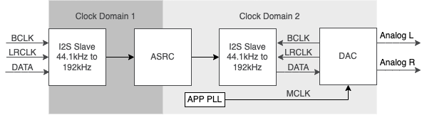
Fig. 1 I²S to I²S Block Diagram#
Fig. 2 depicts a block diagram for the SPDIF build configuration.
It shows the additional S/PDIF transmit function clocked to the I²S clock.
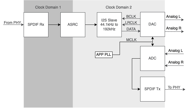
Fig. 2 S/PDIF to I²S Block Diagram#
Fig. 3 depicts a block diagram for the ADAT build configuration. It closely
resembles Fig. 2 with the addition of a de-mux block allowing ADAT samples to
be properly de-muxed based on sample-rate i.e. ADAT S/MUX.
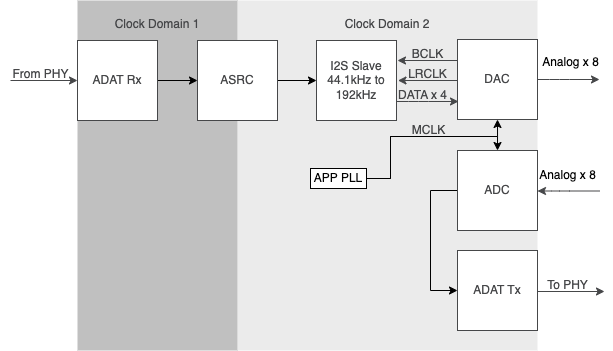
Fig. 3 ADAT to I²S Block Diagram#
Input Interfaces#
I²S#
Inter-Integrated Circuit Sound (I²S) is a serial interface protocol for transmitting stereo, digital audio as pulse-code modulation (PCM) between components. An I²S bus separates clock and serial data signals, resulting in simpler receivers than those required for asynchronous communications systems that need to recover the clock from the data stream - for example, S/PDIF or ADAT.
The xcore implementation of I²S is provided in the interface library lib_i2s.
S/PDIF#
Sony/Philips Digital Interface (S/PDIF) is a type of digital audio interface used in consumer audio
equipment to output audio over relatively short distances. The signal is transmitted over either a
coaxial cable using RCA or BNC connectors, or a fiber-optic cable using TOSLINK connectors.
Both S/PDIF input and output interfaces are supported by XMOS devices using the lib_spdif
interface library which is compliant to IEC60958.
In this application the S/PDIF interfaces used offer two-channel uncompressed PCM format supporting between 44.1 kHz and 192 kHz with 24 bit sample resolution.
Warning
The optical transmit/receive connectors on the XK-AUDIO-316-MC board are not rated to support
above 96 kHz S/PDIF operation. They may work depending on optical cabling quality and length
but if issues are noticed at higher rates then it is recommended to change to the co-axial
electrical connection which is rated for 176.4 kHz and 192 kHz. This can be done by changing the
port declarations at the top of the main.xc file.
ADAT#
The ADAT Lightpipe, officially the ADAT Optical Interface, is a standard for the transfer of digital
audio between equipment. Both ADAT input and output interfaces are supported by XMOS devices using
the lib_adat interface library. ADAT can run at either a 44.1 kHz or 48 kHz base frequency
offering 8 channels of 24 bit audio or fewer channels at higher data rates according to
Table 2. This follows and is in accordance with the S/MUX (sample multiplexing)
interface extension.
S/MUX Setting |
44.1 kHz base rate |
48 kHz base rate |
|---|---|---|
S/MUX-I |
44.1 kHz, 8 channels |
48 kHz 8, channels |
S/MUX-II |
88.2 kHz, 4 channels |
96 kHz, 4 channels |
S/MUX-IV |
176.4 kHz, 2 channels |
192 kHz, 2 channels |
Thread Diagrams#
The xcore.ai device offers up to 16 hardware threads. The example application uses these threads to instantiate the audio interfaces and run the ASRC processing as well as general control logic. The application is split across two tiles with tile[0] hosting the digital input and GPIO control and tile[1] running the ASRC, I²S and digital output.
I2S Config#
The I2S build configuration supports stereo input samples via I²S.
Fig. 4 depicts a thread diagram for the I2S build configuration.
The I²S slave input interface is clocked via an externally provided bit clock (BCLK) and a left/right clock (LRCLK). No master clock (MCLK) is required. Two input channels are supported in the sample application although this can extended through simple customisation. Since it is a slave interface the clock (and therefore the sample rate) is mandated by the external device driving the clock signals.
The nominal sample rate is automatically detected by the I²S slave handler and changes cause the ASRC to dynamically re-configure to accept the new sample rate. The number of data bits per audio sample is set at 32 bits although this may be modified, as required.
Consequently, the I²S configuration of this application provides a high-quality I²S slave to
I²S slave bridge supporting transport of audio samples from one clock domain to another with support
for drifting clocks and run-time sample rate changes.
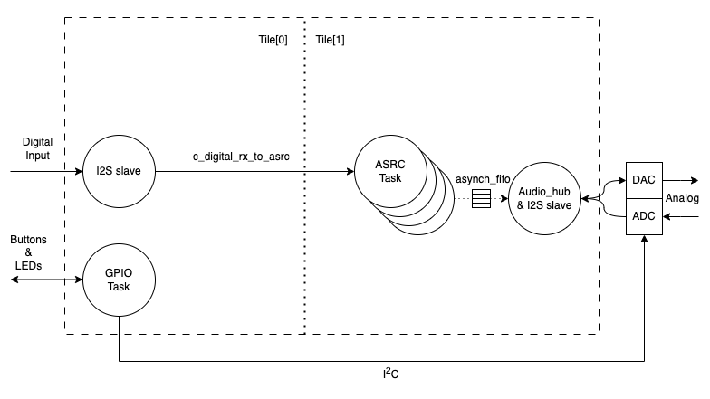
Fig. 4 I²S to I²S Thread Diagram#
S/PDIF Config#
The SPDIF build configuration supports both S/PDIF receive and transmit interfaces.
Fig. 5 depicts a thread diagram for the SPDIF build configuration. Note the
additional thread for S/PDIF transmit functionality.
Both the transmitter and receiver are provided by lib_spdif.
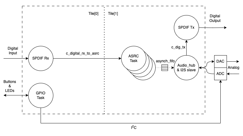
Fig. 5 S/PDIF to I²S Thread Diagram#
S/PDIF Receive#
The S/PDIF receive subsystem comprises of a single thread, SPDIF Rx. This thread receives samples and forwards them to the ASRC sub-system. It also detects changes of sample rate and informs the ASRC subsystem of any changes.
S/PDIF Transmit#
The transmit path is simpler than the receive path since no ASRC is involved. The S/PDIF transmit thread, SPDIF Tx, takes unmodified samples from the I²S “output” bus and transmits them appropriately.
ADAT Config#
The ADAT build configuration supports both ADAT receive and transmit interfaces.
Fig. 6 depicts a thread diagram for the ADAT build configuration. Note the
additional thread for de-muxing the incoming ADAT sample stream transmit functionality.
Both the transmitter and receiver are provided by lib_adat.
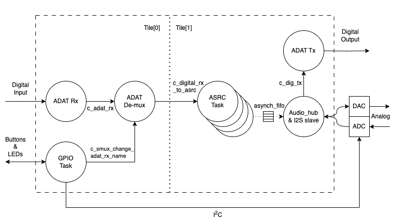
Fig. 6 ADAT to I²S Thread diagram#
ADAT Receive#
ADAT receive consists of two threads. The first thread is the ADAT receive library component. This provides one index frame and eight 24 bit samples over a channel at rate of 48000 or 44100 times per second (a total 432000 or 396600 items received per second). The sample data represents either 8 channels at the base sample rate (SMUX-I) i.e. no multiplexing, 4 channels at double the base sample rate (SMUX-II) or stereo audio at quadruple the base sample rate (SMUX-IV) depending on the S/MUX setting.
The de-multiplexing of these samples is handled by a second thread which also establishes the sample rate and channel count from a combination of the received stream user bit and external S/MUX setting to select between S/MUX-II and S/MUX-IV. It then passes on a group of samples to the ASRC one sample period at a time. A double buffer is used which allows filling of one buffer at the ADAT receive library component rate and emptying of a sample frame at a time.
Note
S/MUX-IV is a logical and reasonably established “unofficial” extension to the specification(s). As such there is no specifed method to determine S/MUX-IV setting from the encoded stream.
ADAT Transmit#
ADAT Transmit has a more straightforward interface. The ADAT transmit component is able to accept either individual samples over a channel or a pointer over a channel to a buffer holding a complete sample frame. Using the latter option means it is possible to communicate with it at the same rate as the I²S (i.e. the sample rate, rather than a multiple of), greatly simplifying the interface. This removes the need for a separate decoupling task between the ADAT Tx and I²S threads. The S/MUX setting is determined automatically depending on the sample rate of I²S and the S/MUX re-ordering is handled when the samples are transferred.
It should be noted that the ADAT transmit component requires a master clock running at either 256 times or 512 times the base ADAT sample rate. This is required for proper timing of the output transitions and supporting the underlying 12.288 Mbit/s or 11.2896 Mbit/s data rate.
An incoming master clock is assumed to be provided along side the output I²S interface.
Using lib_sw_pll and the xcore application PLL it would be possible to recover the master
clock from the received I²S clocks if the master clock signal is not available, however, this is
beyond the scope of this document.
ASRC Subsystem#
Regardless of input interface choice, the samples received are Asynchronously Sample Rate Converted.
The main consideration is that the ASRC function requires a precise ratio between input and output rates. For example, consider the case of converting 48kHz to 96kHz in a synchronous system: the input:output ratio is precisely 2, but for an asynchronous system this could be 2.000001, for example.
To facilitate the calculation of this ratio, timing information must be extracted from the incoming and outgoing streams. This is achieved by time-stamping the input/output samples using the on-chip 100 MHz reference clock, via a timer. These timestamp are passed on to the ASRC to allow it to infer the precise ASRC input/output ratio required. Note, the accuracy and stability of this calculated ratio will have direct consequences on the quality of output.
Whereas for every call to an SRC function in the synchronous case of the previous example, for 1 input sample we would expect to always be provided with 2 samples. For the asynchronous case we would expect to mostly be provided with 2 samples, but occasionally be provided with 3.
This presents two issues: firstly, any buffering scheme needs to deal with this non-uniform sized read/write access. Secondly, this rate needs to be tracked/calculated - typically this involves some sort of controller.
An “asynchronous FIFO” API in lib_src provides both the required buffering and controller, this
is located in asynchronous_fifo.h. The asynchronous FIFO allows read/write from separate threads
- though they must be on the same tile. This shared memory access denoted by the buffer in shown
in Fig. 4 etc.
With all this considered, integrating an ASRC is a non-trivial task. A convenience API is provided that wraps both the asynchronous FIFO and the actual SRC operations, this is located in src_task.h.
The ASRC task wraps up the core ASRC function with all of the other lower level APIs (eg. FIFO) and required logic for sample rate changes and thread scheduling. It provides a simple-to-use and generic ASRC conversion block suitable for integration into practical designs and is utilised in this app note.
For full documentation of the ASRC task API, please refer to lib_src.
Note
Inputting non-sinusoidal 0 dB FS signals into the ASRC can potentially cause clipping in the filter banks
due to the Gibbs phenomenon. To account for
this a pre-ASRC attenuate, post-ASRC gain stage of 1 dB is included. This may be disabled if
not required by setting -DAPPLY_PRE_POST_GAIN=0 in the CMakeLists.txt makefile.
I²S Slave Output#
All configurations support an I²S slave output interface.
The I²S slave interface is clocked via an external bit clock (BCLK) and left/right clock (LRCLK). Up to eight channels input and output are supported via up to four data lines in each direction. Because it is a slave interface the sample rate (and therefore the clock) is controlled via an external host.
The I²S slave component (lib_i2s) has callbacks for the following events which are handled by
the audio_hub() task function:
Initialisation: This where setup code can be run. There is no timing constraint for this callback and so is suitable for relatively slow function calls such as I2C setup if needed. ADAT Tx or S/PDIF Tx is initialised within this callback if used. Additionally a mute counter is set to a nominal amount of milliseconds (250 default) to ensure artifacts created at startup are not passed on to the output.
Restart: This is called at the start of each frame to check whether I²S should break and restart (for example if a stream setting changes). Because this is the first callback to be called within each frame, it is a good place to record the timestamp which is needed for the ASRC since the jitter introduced by variable instruction timing is minimised.
Receive: This callback provides the application with samples that have been received on the I²S data lines. In this application this callback also forwards the received samples to ADAT or S/PDIF Tx when present.
Send: This callback requests the application to provide samples that will be sent out on the I²S data lines. These samples are pulled from the FIFO which is filled with samples from the output of ASRC. Additional logic is added to this callback to estimate the sample rate of the I²S slave. This information is used to decide whether or not to reconfigure the ASRC on the event of an I²S sample rate change.
The Restart, Send and Receive callbacks together must all complete within the I²S sample period otherwise synchronisation will be lost with the incoming interface. It follows then that all but the Initialisation callback must be kept short in terms of execution time. For example, when running at 192 kHz the total time for these callbacks must be less than 5.2 microseconds. This equates to 390 instructions of a 75 MHz thread or 624 instructions of a 120 MHz thread (but note that the I²S IO operations use ~100 of these instructions). The supplied example is easily capable of running at 192 kHz with a 600 MHz xcore.ai clock speed.
GPIO and Control#
The I²S master interface is provided by one of the DACs on the XU316 Multichannel Audio board
(XK-AUDIO-316-MC). The master clock for this is provided by the Application PLL in the xcore.ai
device in a free running mode which is derived from the xcore system clock.
The DACs are configured by the GPIO task via audiohw.xc. This sets the master clock (either
24.576 MHz or 22.5792 MHz) and configures the DACs to required sample rate. This allows the received
and ASRC converted digital stream (S/PDIF or ADAT) to be monitored on the analog output jacks (up
to eight channels for ADAT or two for S/PDIF or I²S). It also configures the ADCs which allow an
input signal path via the analog jacks which will be reproduced on the ADAT or S/PDIF output.
The sample rate for the local I²S master is set by button 2. Each press of this button cycles the I²S master sample rate through 44.1 kHz -> 48 kHz -> 88.2 kHz -> 96 kHz -> 176.4 kHz -> 192 kHz and then back to 44.1 kHz. The default setting is 44.1 kHz.
The rate is automatically detected by the I²S slave logic and therefore, to deploy this example in a real system, the I²S master and DAC/ADC config need only be deleted and appropriate external connections be made to your system. LED 0 flashes to indicate the set I²S master rate where one flash means 44.1 kHz, two flashes indicating 48 kHz right up to six flashes which indicates 192 kHz
The only other control is the ADAT receive S/MUX setting valid for the ADAT build only. This is set by button 1 and indicated by LED 3. Each press of the button cycles the S/MUX setting through SMUX-I (one flash) -> SMUX-II (two flashes) and SMUX-IV (three flashes). The default setting is SMUX-None.
In the case of S/PDIF receive or I²S being chosen as the input source, the sample rate is automatically determined and LED 3 indicates the detected sample rate. It flashes to indicate the incoming sample rate between one flash means and six flashes meaning 44.1 kHz to 192 kHz.
Building the Application#
The following section assumes you have downloaded and installed the XMOS XTC tools (see README for required version). Installation instructions can be found here. Be sure to pay attention to the section Installation of required third-party tools.
The application uses the xcommon-cmake build system as bundled with the XTC tools.
The an02003 software zip-file should be downloaded and unzipped to a chosen directory.
The file CMakeLists.txt contains build configurations named I2S, SPDIF and ADAT.
To configure the build run the following from an XTC command prompt:
cd an02003
cd app_an02003
cmake -G "Unix Makefiles" -B build
All required dependencies are included in the software download, however, if any are missing it is at this configure step that they will be downloaded by the build system.
Finally, the application binaries can be built using xmake:
xmake -j -C build
The application uses approximately 20-25 kB on Tile[0] and 70-77 kB on Tile[1] of 512 kB on each tile with debug printing enabled.
When browsing the source code you will noticed blocks of code that are optionally compiled based on the build configuration, for examples:
#if (CONFIG == ADAT)
    // Some code
#endif
Running the Application#
This application is designed to run on the xcore.ai XK-AUDIO-316-MC kit.
Hardware setup#
The ADAT and SPDIF build configs require no modification of the XK-AUDIO-316-MC board.
Simply run the firmware and connect a digital audio input to the optical IN connector and
the received and sample rate converted audio can be monitored on the analog 3.5 mm output jacks.
Similarly audio played into the analog 3.5 mm input jacks can be monitored (not sample rate converted) on the optical digital output.
For the I²S build it is necessary to connect the input of the I²S slave to an external I²S master. The voltage level of the IO is 3.3 volts. It may be necessary to solder headers if they are not already populated. The default pin-out for the I²S input connections is shown in Table 3:
Function |
Label on XK-AUDIO-316-MC |
Connector number |
Pin number |
|---|---|---|---|
LRCLK |
WORD CLK TERM ENABLE |
J30 |
1 |
BCLK |
PLL_SYNC |
J43 |
2 |
DATA IN |
X0D34 |
J43 |
1 |
GND |
GND |
J43 |
4 or 7 |
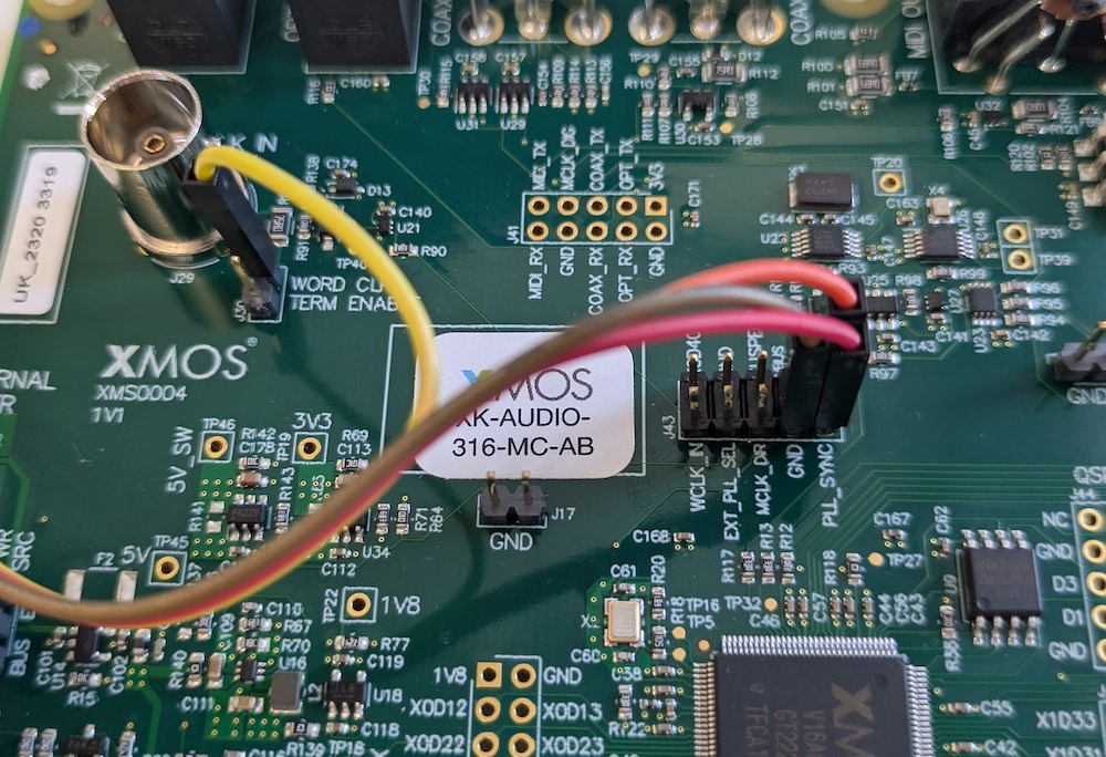
Fig. 7 Connecting I²S input#
Running the firmware#
To run the ADAT build of the application return to the /an02003/app_an02003 directory and run the following command:
xrun --xscope bin/ADAT/app_an02003_ADAT.xe
By default debug output will be emmited to the terminal:
ADAT Rx TO I²S SLAVE
...
The numbers shown at the end represent the maximum number of 100 MHz timer ticks needed by the ASRC processing. A few lines above is the ASRC process_time_limit. Plenty of processing headroom should be noted.
To run the SPDIF or I2S build of the application return to the an02003 directory and run the following command:
xrun --xscope bin/SPDIF/app_an02003_SPDIF.xe
or:
xrun --xscope bin/I2S/app_an02003_I2S.xe
Characterisation#
Signal to Noise Ratio (SNR) and Total Harmonic Distortion (THD)#
The underlying THDN of the ASRC function is in excess of -130 dB with an SNR of greater than 135 dB. However, the performance is slightly reduced by the control loop in the Asynchronous FIFO which will add a little jitter depending on application clocks asserted to each of the digital audio interfaces.
A practical measurement of the S/PDIF to I²S using an Audio Precision Analyser using the XK-AUDIO-316-MC board with a good quality digital source clocks showed a THDN of better than -120 dB.
For further quality metrics please see documentation provided with lib_src.
Latency#
The latency shown by this application depends on many factors:
Input sample rate (dynamically variable)
Output sample rate (dynamically variable)
FIFO sizing (statically set). The FIFO length is currently set to 80 sample frames (all channels per sample period) to accommodate the worst case requirement. The delay added is nominally half of the FIFO length.
ASRC filter stages latency (fixed)
ASRC sample processing block size (default of 4 which is the minimum for the ASRC)
Table 4 below shows that this range is between 0.33 and 1.9 milliseconds for the given configuration in this application. The figures for all build configurations are very close (within 5%) so a single table is provided. The latency was measured at digital sample ingress to the point of egress at I²S following ASRC processing.
Output rate |
|||||||
|---|---|---|---|---|---|---|---|
44.1 kHz |
48 kHz |
88.2 kHz |
96 kHz |
176.4 kHz |
192 kHz |
||
Input rate |
44.1 kHz |
1.84 |
1.7 |
1.3 |
1.27 |
1.1 |
1 |
48 kHz |
1.8 |
1.62 |
1.26 |
1.2 |
1 |
0.98 |
|
88.2 kHz |
1.78 |
1.72 |
0.88 |
0.85 |
0.64 |
0.63 |
|
96 kHz |
1.82 |
1.67 |
0.91 |
0.8 |
0.62 |
0.61 |
|
176.4 kHz |
1.85 |
1.81 |
0.8 |
0.73 |
0.35 |
0.34 |
|
192 kHz |
1.9 |
1.73 |
0.72 |
0.7 |
0.34 |
0.33 |
FIFO sizing is important as it trades off maximum output sample rate, allowable PPM difference (between input and output frequencies) and latency; it is nominally set to 80 for cases requiring 44.1 kHz -> 192 kHz.
For example, setting the FIFO length to 18 (suitable for 44.1 kHz / 48 kHz input and output rates with an allowable PPM difference of 250) the latency of the application can be reduced from around 1.8 milliseconds to 1.1 milliseconds which equates to a 38% reduction, a helpful improvement for some applications. Similarly the 192 kHz to 192 kHz latency can be reduced from 0.33 milliseconds to 0.24 milliseconds by reducing the FIFO depth to 34.
The documentation provided with lib_src contains full details regarding how to size and optimise
the FIFO length for a particular application.
Power Consumption#
The xcore.ai core power consumption was measured for various configurations supported by this application note. In general, higher input and output rates result in higher power consumption. For the ADAT build configuration the results are a little more complex because lower ADAT input rates support a higher number of audio channels to be sample rate converted and also support eight channels of I²S input and output. In general, the core power consumption to be expected for the S/PDIF and I²S build configurations is between 126 mW and 183 mW with the ADAT build configuration being between 161 mW and 205 mW. All configurations when idle (no input) showed a core power consumption of around 118 mW.
Output rate |
||||
|---|---|---|---|---|
44.1/48 kHz |
88.2/96 kHz |
176.4/192 kHz |
||
Input rate |
44.1/48 kHz |
126 |
135 |
148 |
88.2/96 kHz |
140 |
148 |
161 |
|
176.4/192 kHz |
157 |
170 |
183 |
Output rate |
||||
|---|---|---|---|---|
44.1/48 kHz |
88.2/96 kHz |
176.4/192 kHz |
||
Input rate |
44.1/48 kHz |
161 |
174 |
205 |
88.2/96 kHz |
157 |
174 |
196 |
|
176.4/192 kHz |
166 |
179 |
205 |